
Yesterday I did some improvements to the “fixed” 20m FT8 “Hulaloop” magnetic loop antenna.
I’ve insulated the end of the capacitor coax thoroughly, by folding the braid back a bit while sealing it with shrink tubing. I also reshaped the pickup coil from oval to more circular shape. The oval shape appears to give a wider bandwidth but higher SWR, while the circular shape lowers the SWR but also narrows the bandwidth.
Folding the braid back affected the total capacitance, and made the antenna resonate at 14.090 MHz instead of the target 14.074 MHz. Since capacitors in parallel are Ctot=C1+C2, I soldered an insulated solid copper wire on top of the antenna, which can be bent into position to give the extra capacitance needed. After a minute or two of trial and error, the antenna was back to its target frequency and the results were good:
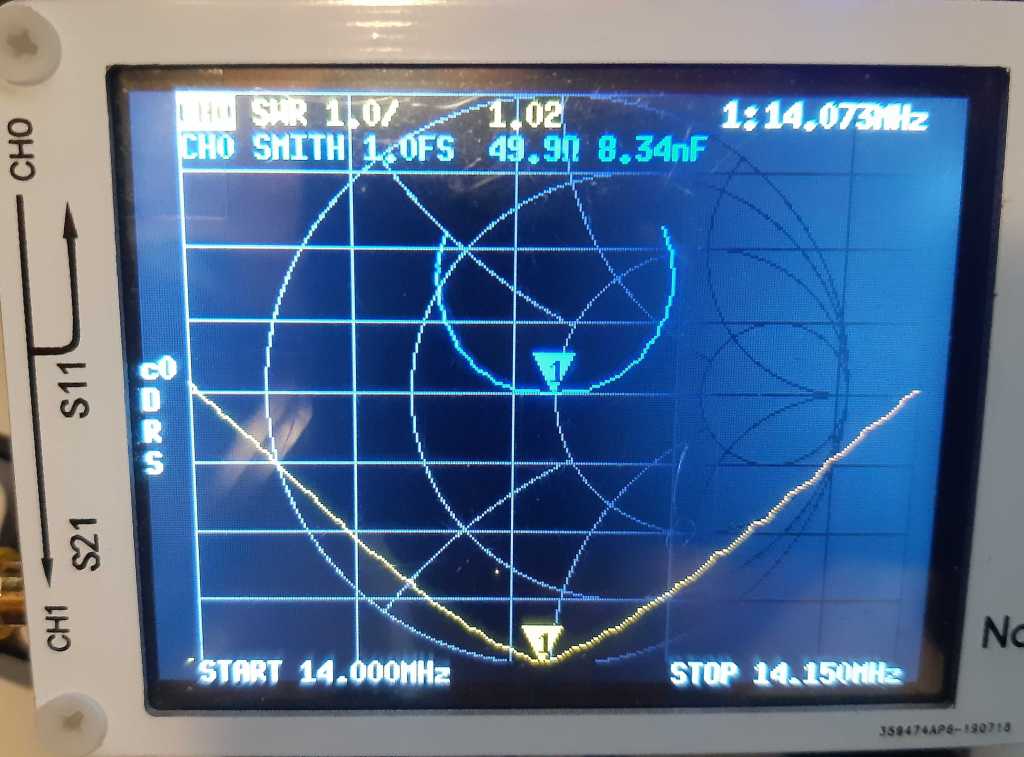
According to the NanoVNA, which my FT-950 seems to agree with, the SWR is now at a record low 1.02, with an impedance of 49.9 ohms! Workable bandwidth is now around 10kHz.
Unfortunately, like always, I did this late night when the 20m band was dead, so I’ll have to wait for an opening to give it a proper test. With the braid folded back, I should – at least theoretically – be able to apply a bit more power than before.
Magnetic loop antennas can build up a massive voltage, expect several thousands of volts if you apply 50 watts or more to it. Since the RG58 I’m using has a rating of around 2000 volts, I may have to replace it with RG213 later, which handles up to 5000 volts.
More reports to follow shortly.
