I accidentally fried my KL405V during my trip to Svalbard earlier this year. About a month ago I was browsing for replacement transistors, and stumbled across a seller on eBay with lots of HG branded SD1446 transistors for a reasonably low price. I’ve read warnings about all about the fake transistors you buy out there, however the seller’s reviews were good so I took a chance and purchased a matched pair for US $50.
I expected two clingfoil-wrapped knockoffs in a small envelope, but my skepticism was put to shame when the package arrived. Professionally packed, labelled with lot number, wafer ID, and properly sealed in anti-static packaging.
The old transistors were clearly damaged, thus removed with great care. If you didn’t know, these guys come with a free surprise dose of beryllium oxide inside, or “poison” as the adults call it. I hopefully did it right since I haven’t died yet. I did get some help from LA9QV Stein-Olav desoldering the first transistor; an extra pair of hands is good to have when you need hot air, tweezers, and a soldering iron at the same time.
Before fitting the new transistors, the surface areas were cleaned. Old thermal paste was wiped away, and blobs of solder removed with a sucker and some wick. I received good help here from LA4SM Steffen, who happily stepped in with his helping hands and priceless experience.
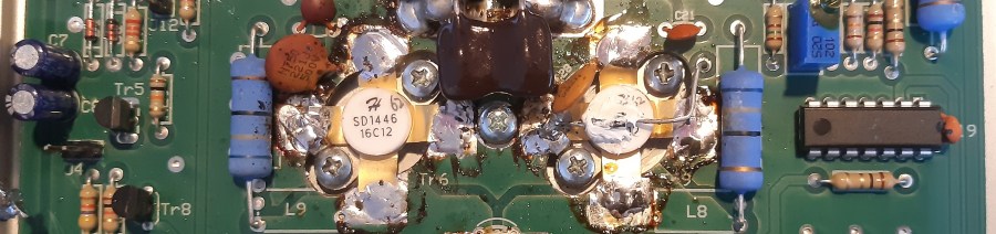
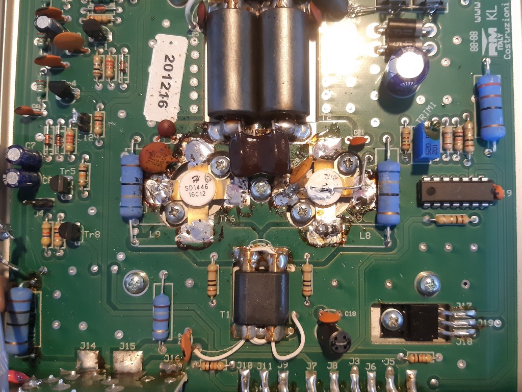
First a dab of fresh thermal paste was coated on, and we started by test-fitting the transistors. They were securely mounted and then removed again, in order to verify that the paste had been applied evenly all over, without any visible gaps or air bubbles. Once we were happy with the coating, the transistors were then pinned down (as they “give” a little due to having a mounting point slightly lower than the PCB) and finally soldered into place. This takes a little work with a proper chisel tipped soldering iron: there are many ways for the heat to sink, not to mention the big surface areas needed to heat up.
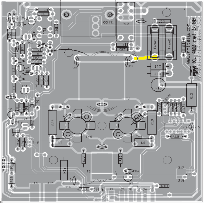
It was now time for the first test run, but it turned out to be a disappointment. The output reading was 0 watts – wouldn’t even give you a RF burn if you licked it. I thought to myself I’ve been scammed with fake transistors, but it turned out to be yet another issue on my side: this time, a consequential problem, probably due to the transistor burnout. The trace from L7 to the fuse bank (as seen to the right, highlighted in yellow) was open circuit. No shorts could be measured thus no point tearing everything apart to find out what, or even why. Adding a bodge wire was good enough.
The next test run was a success and we finally got a reading on the power meter. We carefully started working our way from the lowest power setting to the highest while keeping an eye on the metrics. The PA gladly pushed 220W out from just 8W SSB input. It’s supposedly capable of producing up to 400W SSB according to spec, but I’m not going to push my luck any further right now.
“Why? Why not? Are you a chicken?” you may ask. To be honest, it’s not the first time this PA has been under surgery. The first time I accidentally fried two resistors after foolishly feeding it WAY too much input power. Long story short, I ran RTTY barefoot and took a break. Upon returning, I forgot wasn’t using the PA so I switched it on, and kept on pushing 70W of RTTY into it for about a minute – until it started smelling funny. I suspect this is the first time the transistors got knocked around a bit, and may very well be the root cause of the failure I experienced on JW Svalbard.
Fingers crossed it’s going to behave nicely from now on.

Pingback: CQWW RTTY | LB5SH
These SD’s are really something. I pushed unknowingly the voltage to 24 Volts due to unnoticed power supply RCA 2N3055 break down short circuit during QSO and suddenly the power output meter went from 100W (with 5W input) up to 150W turning the heatsink into a hot iron. It survived. Next mishap was when I pushed the SD’s with 25W AM input to getting red hot. Yet they survived again. Even the output transformer went red hot.
LikeLike
Thanks a lot. I will for sure order HG’s replacement transistor for my HLA-150. It looks like a honest seller not faking components, but provides compatible replacement parts.
LikeLike
Hey – here’s a quick update for the interested:
The PA went QRT after a few months after the repair job.
At first glance the new “eBay transistors” worked just fine. They didn’t quite provide the same output power as the original ones, but it was good enough.
However, I don’t really blame it on the transistors: here’s a word of hindsight wisdom for you all. In short, this amplifier really dislikes heavy-duty modes – like FT8. Digital modes can be brutal, and I guess this is what broke the PA in the first place during my Svalbard visit.
If you use this PA exclusively for SSB operation then you’ll be happy with it for a long time.
I’ve later acquired an Ameritron AL-80B, which we all know is a proper tube amplifier. Sure, it weighs enough to sink a medium-sized oil tanker, but on the flip side it can take some *serious* beating and still keep going.
Any operators can mistakes, especially when they’re tired. DXpeditions are super exhausting, so any PA in my service must to be able to take a bit of abuse without calling it quits.
LikeLike