In the northern part of Norway we don’t have the luxury of 24/7 6m openings (I’m looking at you, Central Europe!) so whenever the allmighty RF gods sprinkle us with dopamine inducing sporadics, we need to be prepared and on the alert. So, therefore, my friend Kajetan (LA8WJA) and I teamed up to build each our 6m delta loop to play with, and to be honest I found the results quite impressive.
“Impressive, how?”
I’ve been toying with delta loops before, so I had a rough idea of what to expect. Mostly symmetrical 200ohm types, but the overall impression have always been “why don’t I use delta loops more often?”
Considering the time and money spent to get this thing up and running, I would be happy with almost anything.
Take this with a grain of salt since I have not done any simulations and only tested it in real life, but the claimed gain on such an antenna is said to be somewhere between 2.5 and 4 dBi. While your milage may vary, depending on a range of variables, I think it’s reasonably safe to estimate somewhere around 3 dBi. Ish.
Want to build one? Here’s how you do it.
Disclaimer: This build is based on various findings on the internet, and I am not claiming any credit for this work. There are many other websites out there explaining how this antenna works and how it’s built – if anything is unclear, just google around and you’ll find answers.
Build time: 20 minutes. Seriously.
Parts needed:
– SO239 connector, or a coax stub
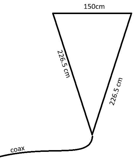
– 603 cm wire
– 150cm non-conductive support material like PVC pipe
– PVC alternative: use rope to suspend the top with equivalent spacing
Antenna specs:
– Impedance: 50 ohms, no balun required
– Bandwidth: ≥500 kHz
– Measurements: Tuned to ~50.3 MHz
– SWR: ±1.1
This specific shape, like an enlonged triangle shown here, gives an antenna impedance of 50 ohms, and will instantly match the rest of your network.
Feed point can be as low as 1 meter above ground
Here’s a picture from testing my first build. I used a 16mm plastic pipe for electrical installations for the 150cm run, including bends, because I felt a little fancy that day. I later added a 20mm pipe stub that fit perfectly the balcony flag mount. Feedpoint height here is approximately 1.5 meters above ground. Even this close to the ground and surroundings, the measured SWR was 1.07. That’s not half bad!
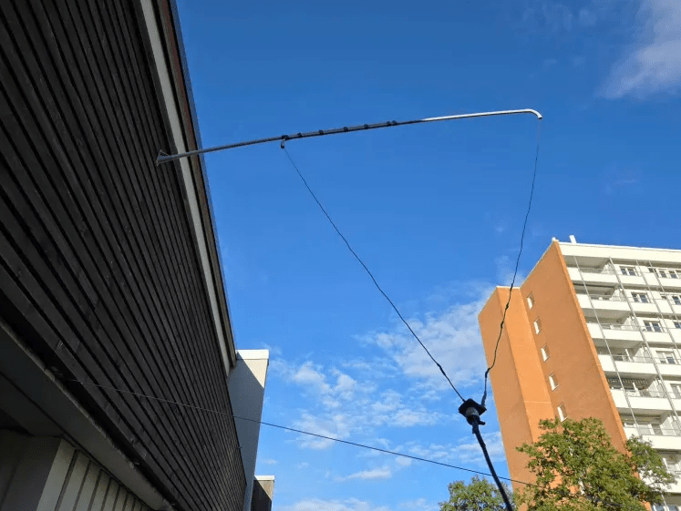
As you can clearly tell there were a couple of trial-and-errors while attempting to find the right length, but this is the prototype anyways so it doesn’t really matter.
So far I’ve fed this antenna with a modest 60 watts, but not a single hiccup have been detected. Fed with RG58 from the shack (which is behind the white panels on the bottom left of the picture above) and not even a choke is needed nor applied.
The bottom-fed design is, according to someone*, effective and will provide good directionality. The direction is “through” the antenna, i.e. if the corners are north-south, the antenna will radiate most energy east-west. Flipping it upside-down might introduce less noise. You can also arrange it in a horizontal configuration for omni radiation, or even tilt it 45 degrees for a bit of both. Mix and match. Do what you like, the SWR won’t change but the radiation pattern will. Experiment, and see what works best for you!
Well? What are you waiting for, get your lazy ass up from the chair and build one yourself!
I’ll finish this post with a tip – if you accidentally used too much wire and it resonates too low, don’t reach for the pliers. You can twist the end up near the base near the SO239, until you find the right tuning frequency. This twisting of the elements will just behave like a part of the transmission line and shrinking the lengths of the elements accordingly.
I thought was a neat trick.
Thanks to Kajetan, LA8WJA, for the peer pressure into finally building it myself.
That’s it for now – time to prepare for the International amateur radio exhibition in Friedrichshafen. It’s actually my first visit, and I’m leaving tomorrow. If you’re going, let’s have a pint!
*) I asked AI. Sorry.
