I had to work my way around a couple of unexpected obstacles. The transistor I used as a “pre-amp” did not perform well enough to work on 17m. The rise and fall time was way too slow, barely being able to perform at 630m / 475kHz. Indeed, that was my target frequency, but being expert on auto-sabotage the goal post had to be moved farther into the unachievable distance. Sigh.
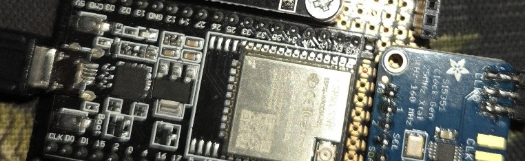
As an experiment, I ordered a handful of various buffer drivers to replace the NPN. First victim, the MIC4422YN from Microchip, was fed directly (via a small resistor) by the Si5351, and a 7809 regulated its power to 9VDC. Success was more or less instant, it worked very well at 630m and 160m without any noticeable issues.
Despite not being the “Ferrari” of buffer drivers, it also operated somewhat adequately on 80m. At 3.5MHz, the duty cycle was a bit off, but produced a loud and clear signal.
Don’t be distracted by this, though. Listen – this thing is actually working! My power meter shows 10 watts during the dummy load tests, meaning what we have on the bench is a real, functional, single-transistor, DIY, tri-bander, class E power amplifier!

(I know, I’m as surprised as you are! I didn’t expect it to work either!)
Attempting to operate at higher frequencies is not even worth trying. Obviously, by making such a bold statement, I’m also admitting to having tried.
Nobody’s asking “why not?”, so I’ll explain in three different ways, from 1 (“dumb”) to 3 (“fine, I get it”)
1) Slow chip goes “brrrrrr”
2) The driver IC takes too long to switch from high to low, or low to high, thus producing garbled output.
3) The frequency is limited by the driver’s rise/fall time, meaning the time it takes for to execute a logic switch. It’s too slow. As the French prime minister of health and security once said, “ceci un example d’extreme*”, so just for this once, let’s pretend we’re both complete idiots trying to push this all the way up to the 10 meter band, 28 MHz. In this scenario, every logic switch must be performed well within a time frame of 35nS, preferably less. Sadly, the MIC4422YN can’t keep up with that. You know, in a way, it reminds me of your mother: slow, cheap, always high on meth. So, if anything plops out the other end, it’s guaranteed to be ugly and unusable.
But fear not, my dear friends**. I have already identified several promising substitutes, being able to do the switcheroo in less than 2nS, reasonably priced but only available as surface mount. I’ve realised I must redesign everything as SMD, and have already started sketching up a new board in KiCad. My goal is to have PCB’s ready to be ordered by the time I get back from the 3YØK DXpedition in early March.
Pics or it didn’t happen, you say? Oof. Brace for impact in three, two, one..
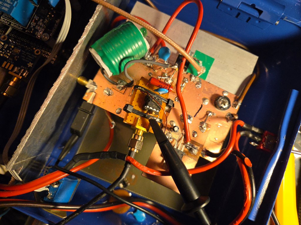
(PS: In the dictionary, under “I had a cool idea but didn’t plan ahead”, you’ll also find this picture)
But hey – ♪fffpweeet♪ !! Don’t look at that abomination any more, let me distract you away from my horrible soldering and total lack of electronics skills. Oh look, scroll down, here’s the reason I haven’t been much on the air lately – you asked about that, remember? Scroll down. Now.

(Bonus points if you can say “rare horror aurora” out loud, in a thick American accent. “Reahrhhruhhrh!”)
Jolly jackhammer Jesus, this post did not end up the way I intended. Holy shit, I’m sorry. I’ll take my meds now and hopefully the next post will be better. One more chance, please?
On the serious side, this project will continue and live on for sure, but right now it’ll have to go QRX for a bit as I’m participating in the 3Y0K DXpedition to Bouvet Island. Hope to find see you in the log!
Until next time, 73 de LB5SH Stian
*) Fine, it’s rubbish, so excuuuse mmmeee for pretending to speak French for a brief moment!
**) Not sure how many friends have left after insulting both you and your mother, but I decided to use the plural form just to give the impression of having more than one.

Hi, i came across your blog and your ham radio project are truly inspring! I’m Emily from PCBWay and I’d love to sponsor your project with free PCB prototyping. A brief review would be appreciated in return. Would you be interested in collaborating?
LikeLike