Results from testing the power amplifier were both uplifting and disappointing.
Let’s get straight to it.
Let’s take the bad news first. The current design use a small NPN transistor to amplify the Si5351’s output signal from a unloaded 3.3V to 13.8V DC to allow the FQP13N10 mosfet to switch as intended. For frequencies higher than the 630m, that didn’t work. I initially tested this at 18MHz, since the 17m band has the lowest SWR on my vertical at home, but to my surprise the NPN would simply output a general average of the pulse trains, and not the actual 18MHz waveforms expected.
Unfortunately I don’t have any actual pictures showing the oscilloscope, so to illustrate the issue you’ll have to trust my MS Paint skills. This shows the RF signal before (top) the NPN, and after (bottom):
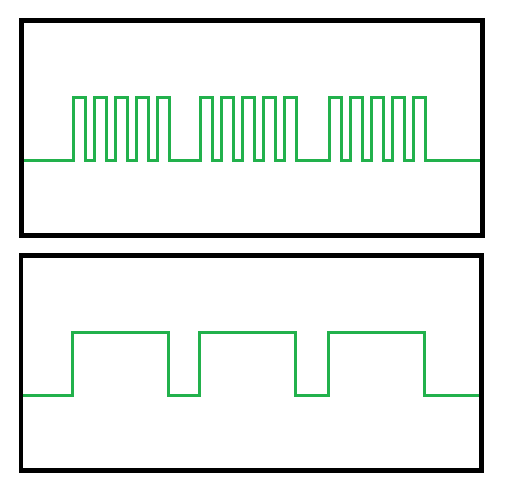
To test this in an isolated environment I replicated this exact section of the circuit on a new board, with identical results. Well, shit.
On the positive side, though, you could say the design works as intended. On 630m, 472-479 kHz, it operates according to the design, so in a way you could say it a success..?

I’ll be damned if I stopped there. I want this thing to work on at least one or two more bands. Mainly to educate myself, in addition to learning more about analog electronics and RF amplifiers. However, if it turns out that I’m too big of a knob, I’ll quietly revert back to 630m and never speak of it again.
The next approach already in the works, and more components are on the way as we speak. This time I’ll substitute the NPN with a proper TC4422 high-speed mosfet driver. From what I gather, the new driver design should allow for 160m activity, and could potentially be pushed to 80m as well.
To complicate things further, I discovered that my antenna suddenly have SWR=3.0+ on every band, so something must’ve happened to it during the new year’s storms we’ve had here. I can only assume the RF gods found the driver approach too easy, and decided to sabotage the project.
Aaah, well played, RF gods.
Well played.
