…to be tested! Hah! You just got click-baited!
But keep reading, though. It might get better down the line.
Let’s have a look at the current state of things. Right off the bat, and to be frank, no real schematics exist yet. Apart from a few sketches in my notebook, it’s more or less built on-the-fly. I went Manhattan style, having one solid ground plane and lots of small “islands” to isolate each node.
One thing, though, and I’ll gladly admit I’m on thin ice here. Maybe – quite possibly – or maybe not – my take on the Manhattan style could introduce unwanted impedance. I don’t know how much or if it have any significance at all, maybe it won’t cause any problems. (Jinx, it will now!)
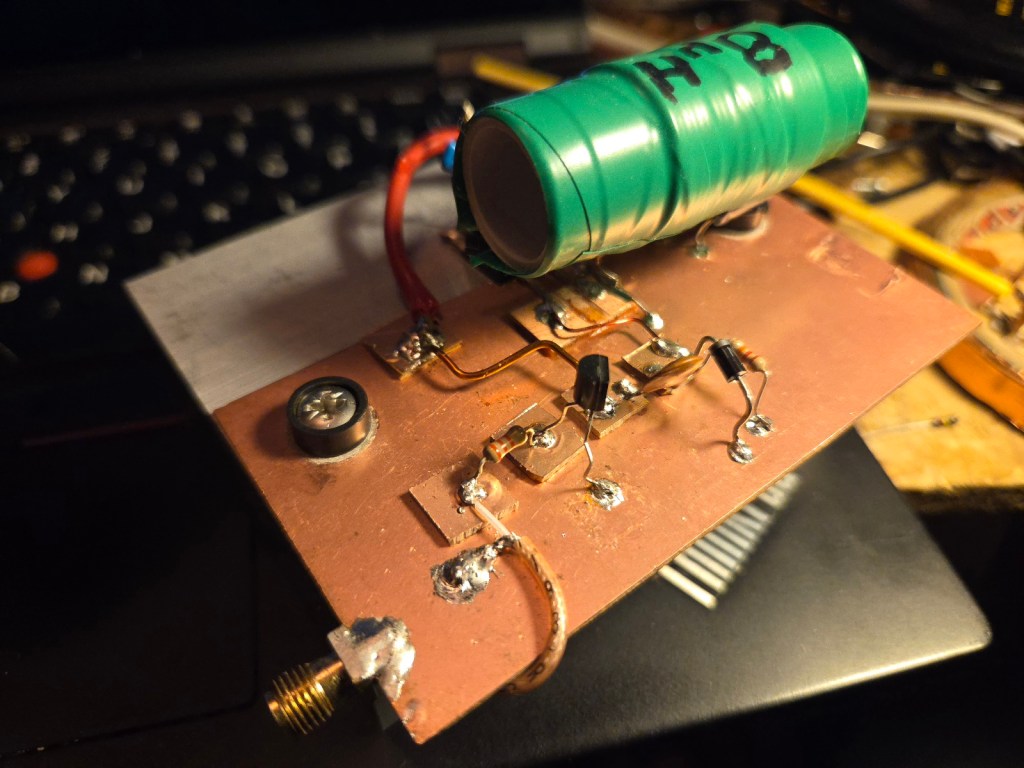
The feedpoint is the SMA connector at the bottom of the image, and is directly connected to the output of the Si5351. This signal lacks the proper oomph to bitchslap the mosfet into action mode, so it first makes a quick detour via a 2N4401 NPN for a quick boost. Keep in mind we’re still dealing with square waves, but considering that we’re building a class E amplifier, that’s actually perfectly fine. No biasing required.
It’s just a really weird on/off switch at this point.
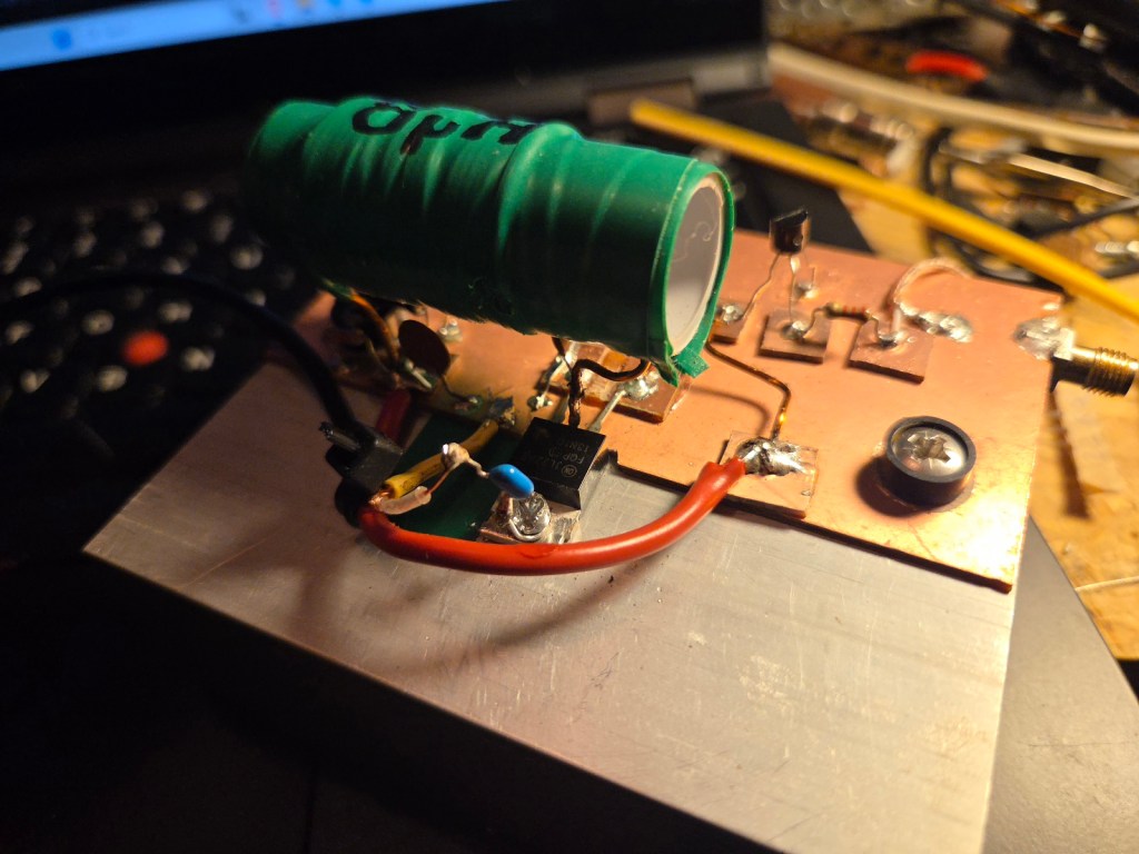
The “green hulk” inductor at 8µH helps to provide enough current when needed. Considering 630m at ~475kHz, the duration of the active state will be surprisingly long, it’s there for good reasons.
The mosfet drain, on the center pin and shorted to the tab, is actually convenient. I’m using both for this build, the DC is smoothed and fed through the inductor to the drain pin in the center, and the tab is where I’m pulling the RF output (via a 50V 100nF DC blocking cap) into 50ohm coax. The idea is that this coax will later feed the waveform smoothing and low-pass filter board, which is the next build.
That said, I guess it’s pretty obvious that what you see here are “bare bones.” Keeping each board separate allows easy debugging, as well as the opportunity to play on higher bands in this test phase. I’m still playing with the idea of supporting multiple bands, and if this works as expected, I’ll have PCB’s made professionally that supports, oh I don’t know, maybe all bands. Who knows.
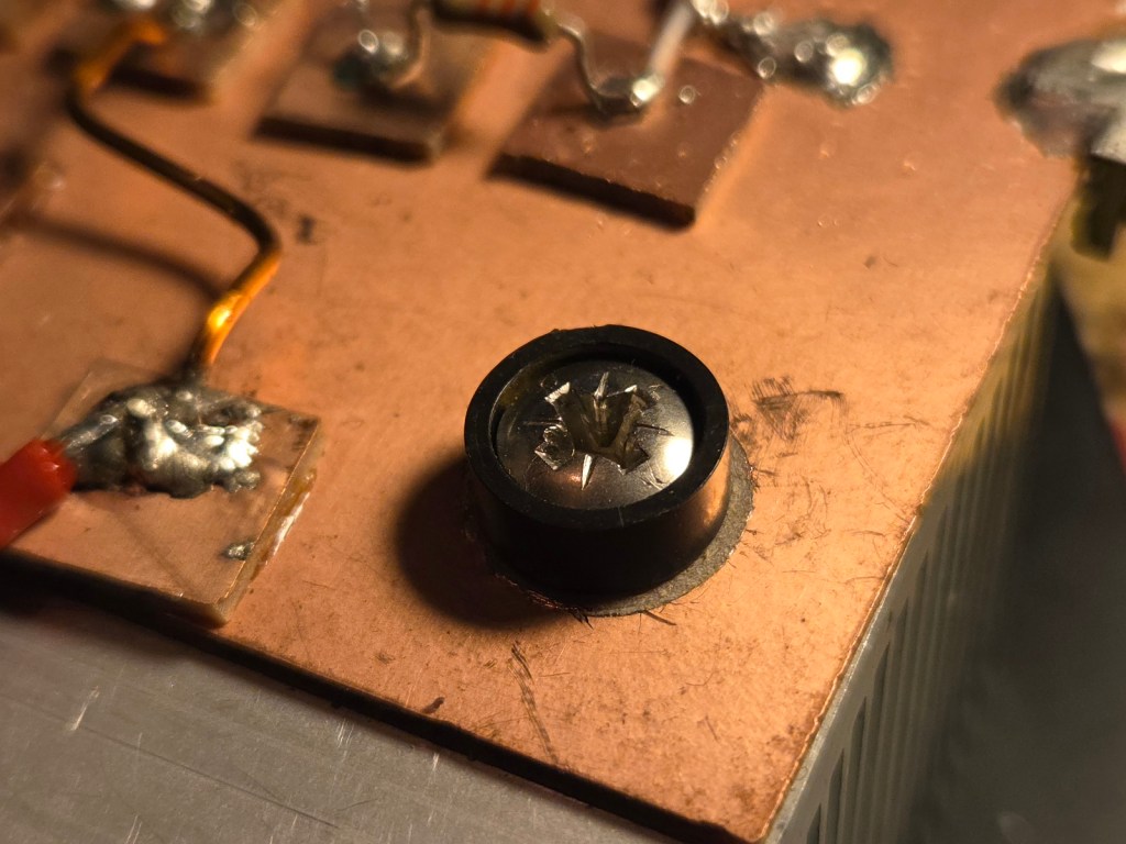
I’m sorry, what was that? Did you say you’re concerned the PCB mounting screws will short drain to ground? Don’t worry, I gotcha fam. The copper is removed under and around the screws, and insulated them with “upside-down plastic caps.”
I’m sure they have a fancier name, but I have no idea what. For now, that’s what they go by.
Next up is testing this on a dummy load to measure the output power, followed by finishing the waveform smoothing and LPF board.
I theory, these mosfets might be configured to work in a parallel configuration. Meaning, let’s say you take it easy running one at 50w, adding another would give 100w. Four in total would result in 200w. I suspect this would require some additional balancing circuitry to compensate for variations between each mosfet, but it shouldn’t be impossible. Really tempting to give it a shot, considering they’re priced like $3/ea or so, but let’s see if I can make it work with one first.
Let’s see if I can get this thing on the air, on one band or another, before the end of the year.
