Don’t be afraid, come on in! Settle down, and join me on this adventure on yet another project, never to be finished!
History
I’ve been playing with the idea of having a QSO on 630m for a very long time now, and it’s about time I do something about it. The challenges are many, and it’s quite the obstacle run to get to the finish line.
Challenges
First off, I don’t have a transmitter for 630m, so I need to build one. Second, I have a back yard the size of a beer coaster, so the antenna must be loaded to the point of comedy value. Third, to compensate for the massive losses in the said antenna, I’ll have to ramp up the power output by building a custom power amplifier for it.
Goal
The ambitious goal of this project is to have one QSO. If I get one (preferably) verified 630m contact in the log I’m happy. However, given all the required work I’ll have to put into this, I want this to be a human-to-human QSO, and therefore the entire circuit is designed as a stand-alone CW transmitter.
The plan
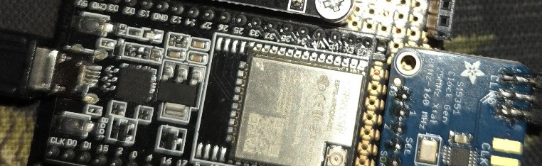
I’ve opted to use an ESP32 as the main controller for this circuit. The adjustable output of 472-479 kHz will be adjusted using a potentiometer, and the signal will be generated by a high-precision <1 PPM Si5351. Finally, a class E amplifier based on FQP13N10 will jack the RF output up to 80 watts (hopefully) which will give a output that’ll reach our EIRP limit of just 1W.
Status
At the time being the code for the keyer is finished. It’s currently fixed at 20wpm, but I might add a second potentiometer at some later point, to be able to adjust the speed of the keyer. Implementing an iambic keyer was surprisingly challenging, given the possible keying combinations and simultaneously maintaining the timing correctly, but I eventually got it working in ~30-40 lines of code. I’ve also added the relay logic, which includes a 1 second tail to each transmission for reducing unnecessary chattering.
What next?
Next stage is probably to start building the class E amplifier, which will be on a separate PCB. The mosfet is already mounted on a oversized heat sink. Since I don’t own a CNC (and too impatient to wait for a PCB order to arrive) I’m attacking this layout in Manhattan style. The component count will be kept to a bare minimum, only featuring the PA and a simple low-pass filter.
Pics or it didn’t happen
Here’s the current state of the main PCB. For prototyping, I’m using various module boards. Big thanks to LB1DK Mikael, my personal hardware dealer, for generously helping me out with the relay module.

Ah, you noticed the buzzer, didn’t you? I brilliantly added this to assist myself while developing the cw keyer logic, and for some reason left it behind as an optional monitoring device.
How I regret this decision. Imagine an industrial fire alarm falling in love with forks on a dinner plate, and they decided to have a baby. Then, this baby falls in love with an angle grinder, and they have a baby together. That’s the buzzer. I bet even the hearing impaired people in my area have been anxiously looking around lately, all disgusted, wondering where the Hell that awful sound came from. I mean, holy shit.
Anyway, stay tuned. Updates on this project will follow!
(…or will they? Who knows, I’m a mystery box full of disappointments)
